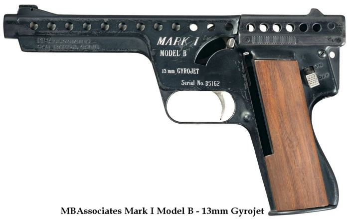
Gyrojets were developed in the mid 1960’s by Robert Mainhardt and Arthur Biehl, founders of MBAssociates. Friend and fellow collector Mel Carpenter wrote a comprehensive book about the history and development of the Gyrojet, called AN INTRODUCTION TO MBA GYROJETS AND OTHER ORDNANCE. I would highly recommend anyone to get this book. Book can be ordered directly from Mel on his website. there is also a very informative YouTube video explaining the mechanics behind the Gyrojet design. All references to images are from Mel’s book. (Erlmeier, Brandt Ref. 177).
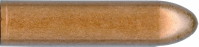
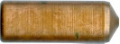
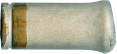
Empty unfinished cases. Right-hand specimen is the longer case design (Fig. 13 – 31(A) p. 160)


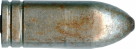
Left specimen with a resin type sealant covering the entire nozzle to prevent moisture entering the cases. (Fig. 13 – 14 (E) p.151)
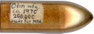
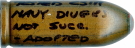
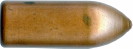
Right-hand specimen is a Bundy Tube loading. Bundy tube was used in the automotive industry and is made of a low carbon copper plated steel strip rolled into a double layered tube into which an aluminium rivet was inserted at the tip. (Fig. 13 – 17(C) p.152). The red tip has no meaning and is not indicative as a tracer. Interestingly, the note on this cartridge state that it was tested by the South African Navy as an anti-shark device.


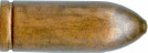
Left specimen is a fired round and has a double cannelure with plain steel tube (Fig. 13 – 36(C) p. 163)
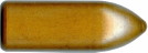
Right-hand specimen has a normal two port nozzle (Fig. 13 – 23(A) p. 156)


Left specimen is called the wad-cutter loading. (Fig. 13 – 18(B) p. 154)
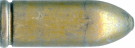
Right-hand specimen with single cannelure and zinc chromate finish (Fig. 13 – 36(C) p. 163)


Left specimen has a four-port nozzle (Similar to Fig. 13 – 23(A) p. 156)
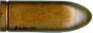
Fired 13mm Bundy Tube Gyrojet with two-tone partial tin plating (Fig. 13 – 39(F) p. 165)

 Early 13mm Gyrojet with 4-port nozzle.


Gyrojet Nozzles. See also Fig 6 – 8 p. 83. First specimen Fig 6-8(J), Second specimen Fig 6-8(K), Third specimen Fig 6-8(L). Fourth and Fifth specimen is the undrilled steel blank Fig 6-8(E).
During the Vietnam War, the standard flares issued to pilots were fired from a Pen Gun. The Pen Gun however had some drawbacks, the biggest being that it was relatively ineffective in dense jungle canopy as well as having a loud report and high recoil. That meant that to in order keep it manageable, the flare only had a maximum height of about 400 feet. The original Gyrojet flares that were developed were to be adapted for the Pen Gun, but were made to be fired from Gyrojet Pistols, so they were the standard 1,4in. in length; the same as the 13mm rockets. The Mk.1 achieved a height of around 750 feet, but the pyrotechnic display lasted only about 4 seconds. The new design was started in late 1965 and the length was increased to 2 inches that could lift a payload of 0.35-ounces up to 1,300 feet, depending on how much foliage it had to travel through. The original flares used the 4 port nozzle. Four port nozzles were more accurate than the 2 port versions, but with a flare accuracy was less important than cost of manufacture, as long as the flare went relatively straight up in the air, so the design was altered to two port nozzles on all 13mm flares.

 Cannelure nozzle crimp with copper plated motor section. (See Fig 15 – 3, p201)
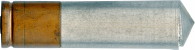
Specimens below are M201/201G (Global) and almost all were red as it was the international colour for distress signals as well as the only one the US Air Force wanted. All specimens have unplated steel motors protected against corrosion by a chemical coating, usually zinc-chromate.

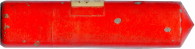 Fig. 15 – 12(i) p. 206
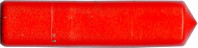 Fig. 15 – 12(i) p. 206

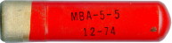 Fig. 15 – 12(f) p. 206